Design Process
From Simulation to Board
This project started because I wanted to build something for my girlfriend for
Christmas. She plays piano, so I thought this would be perfect for her. I did
some research and found an instructables page here
that I pulled heavily from for the schematic design.
Core Operation
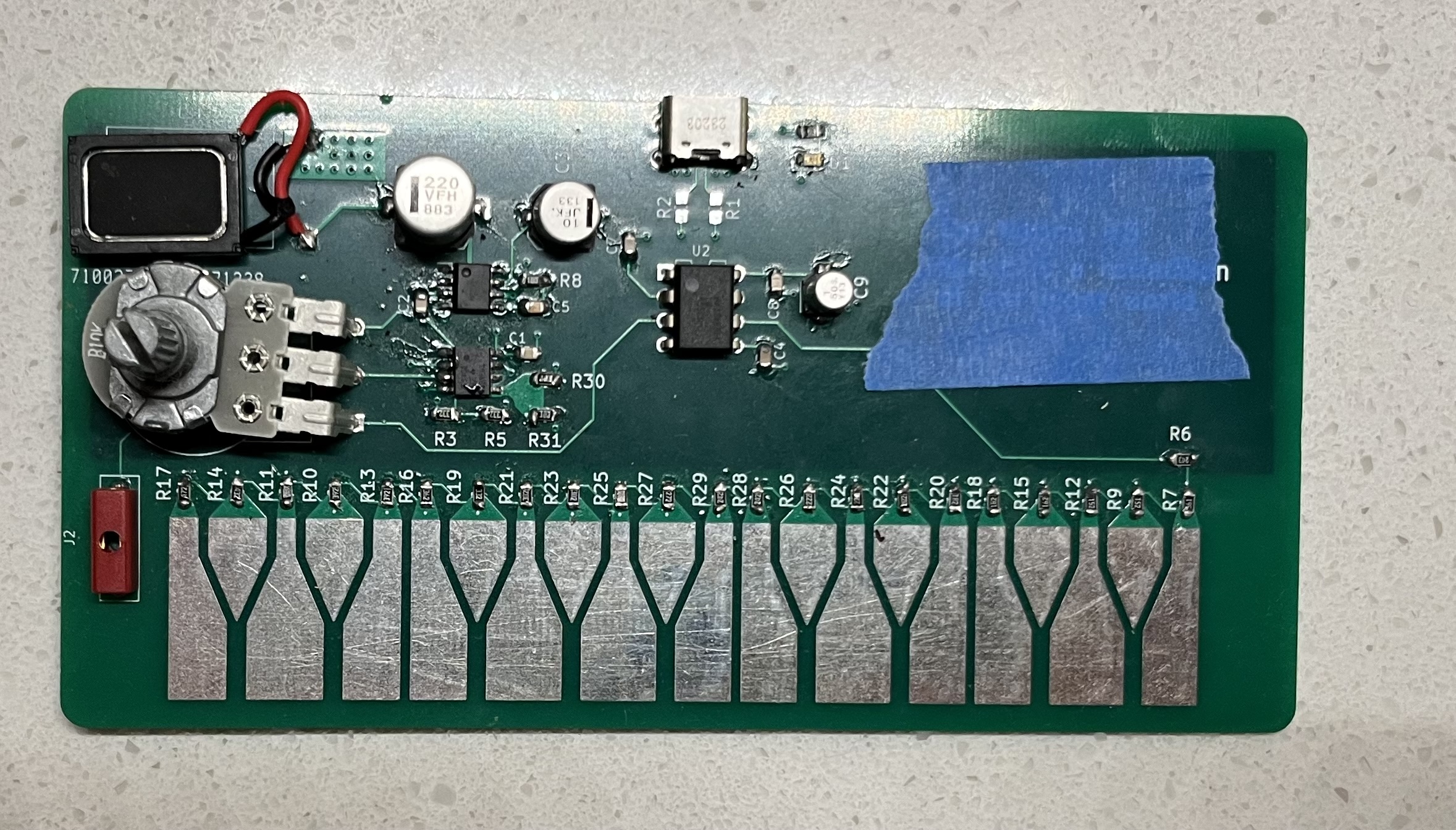
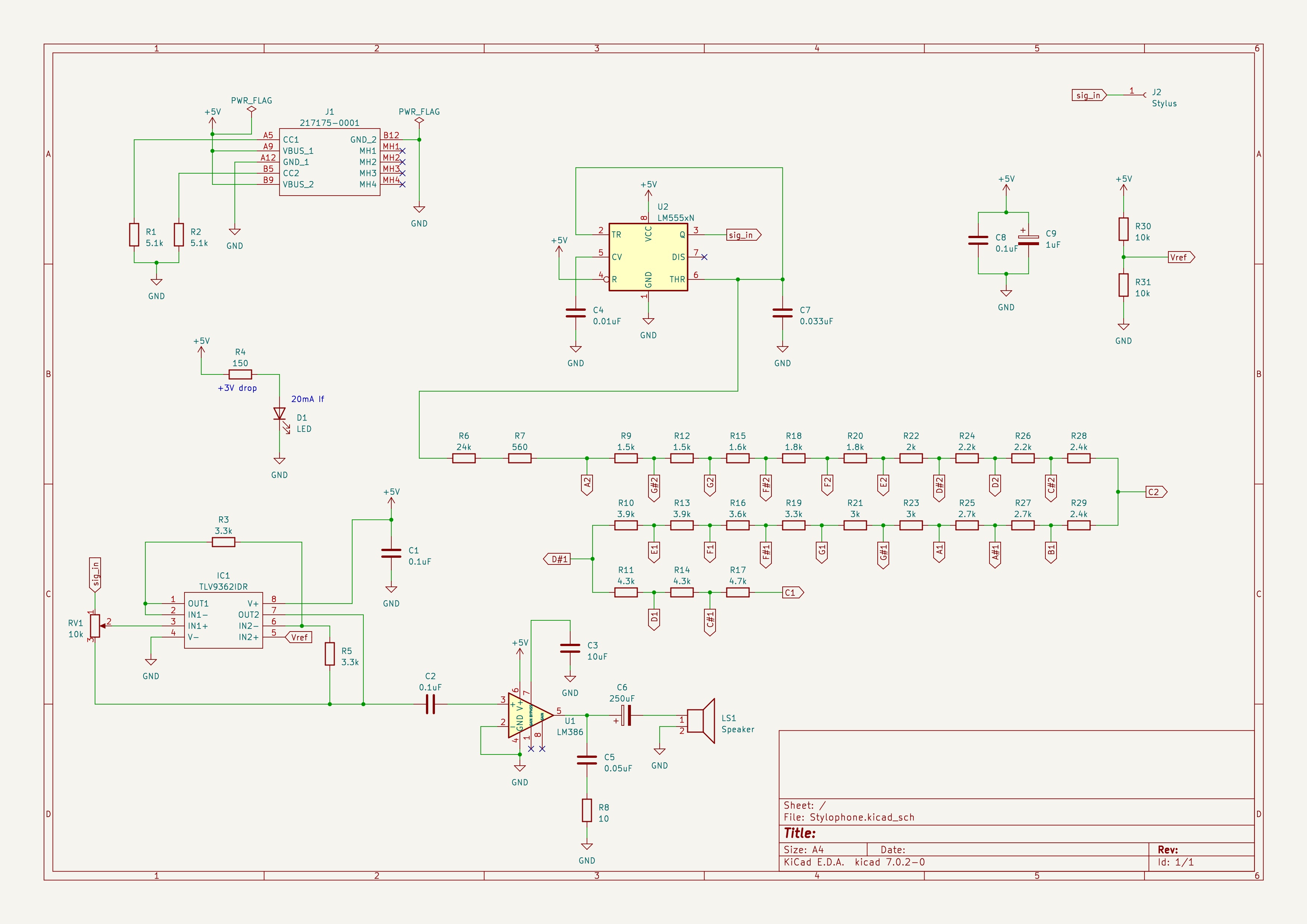
The idea behind the core functionality is that the keys are connected to a resistor on the PCB. When the stylus presses
on a key, it completes a circuit and forms a voltage divider with R6 and R7. That voltage changes based on what key you
press, and the voltage sets the output frequency from the 555 timer. Therefore, by carefully choosing the values of your
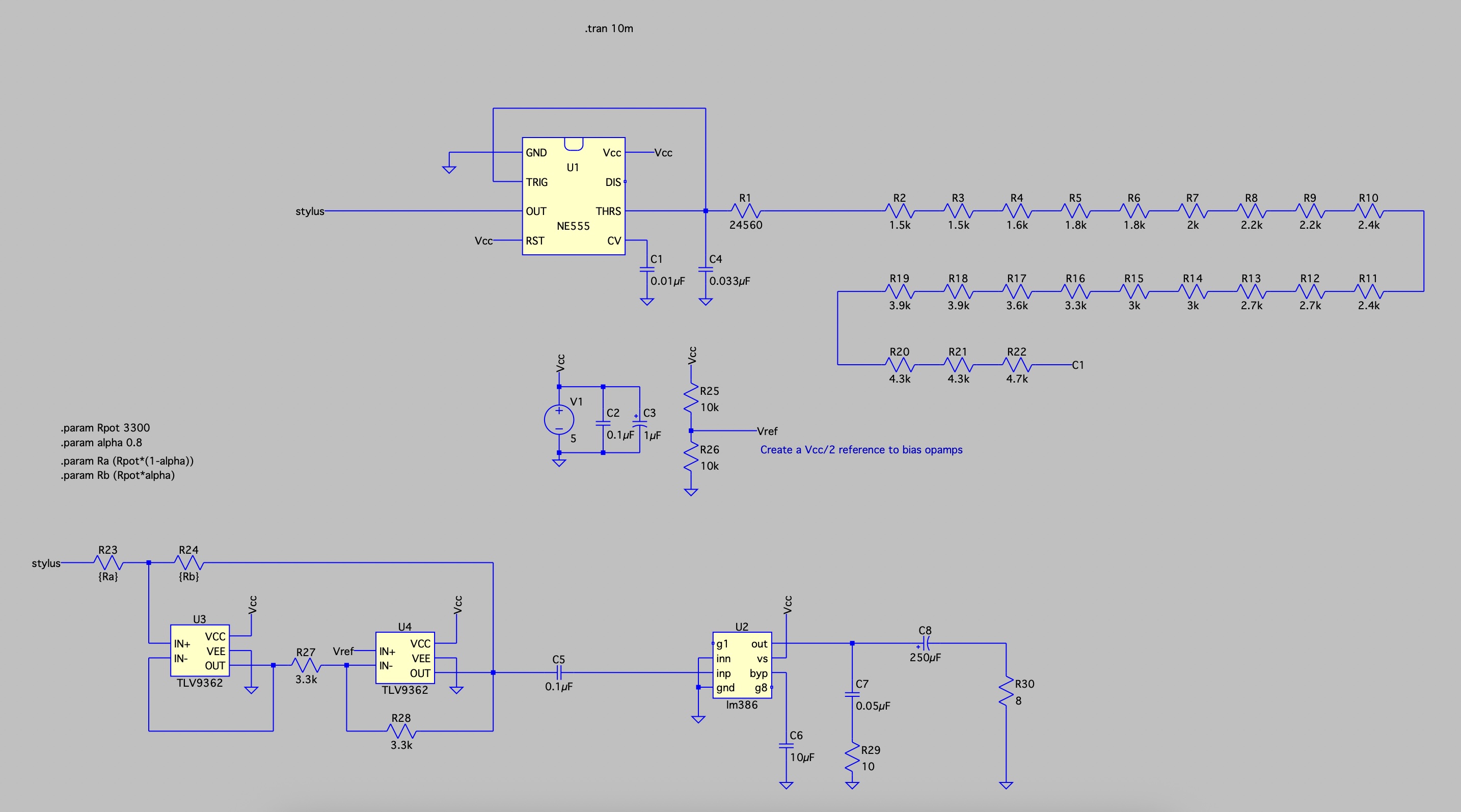
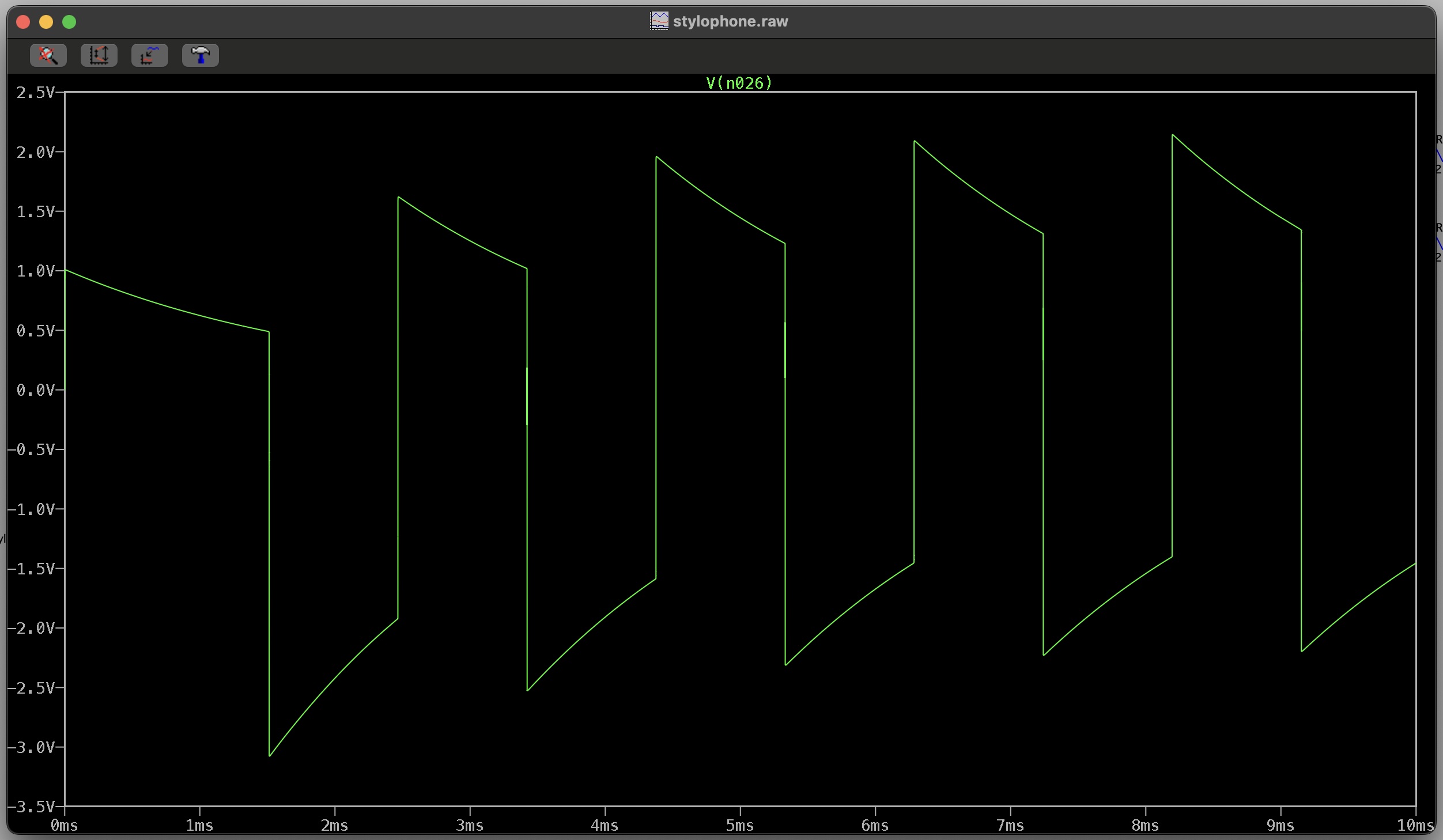
resistors, you can output the necessary frequencies for piano notes. I did an initial simulation in LTSpice to verify
that the circuit functioned as expected before moving on to KiCAD.
Key Finding: For high quality audio, the 555 timer is not the best choice for a
VCO. It is relatively noisy, and can produce high distortion waveforms. Also it only outputs a
square wave, so additional waveforming would need to be done to get different timbres. However,
for this low fidelity application where we just want a buzzing sound at the right frequencies,
it is more than good enough.
Baxandall Volume Control
Baxandall volume control involves adding in two op amps to the standard potentiometer used to decrease
the volume. The high impedance input buffer and inverting output amplifier does two main things: it gives
a linear potentiometer a logarithmic volume response which is better for human hearing, and the transfer
function is not a function of the pot track resistance or any other discrete resistances.
Output Stage
The output stage includes an LM386 audio amplifier and a 1W speaker. The LM386 was chosen because a single ic
can supply enough current on the output to drive the 1W speaker, and it is relatively simple to set up, requiring
only a few peripheral components such as decoupling and input/output capacitors to block DC.
PCB Layout
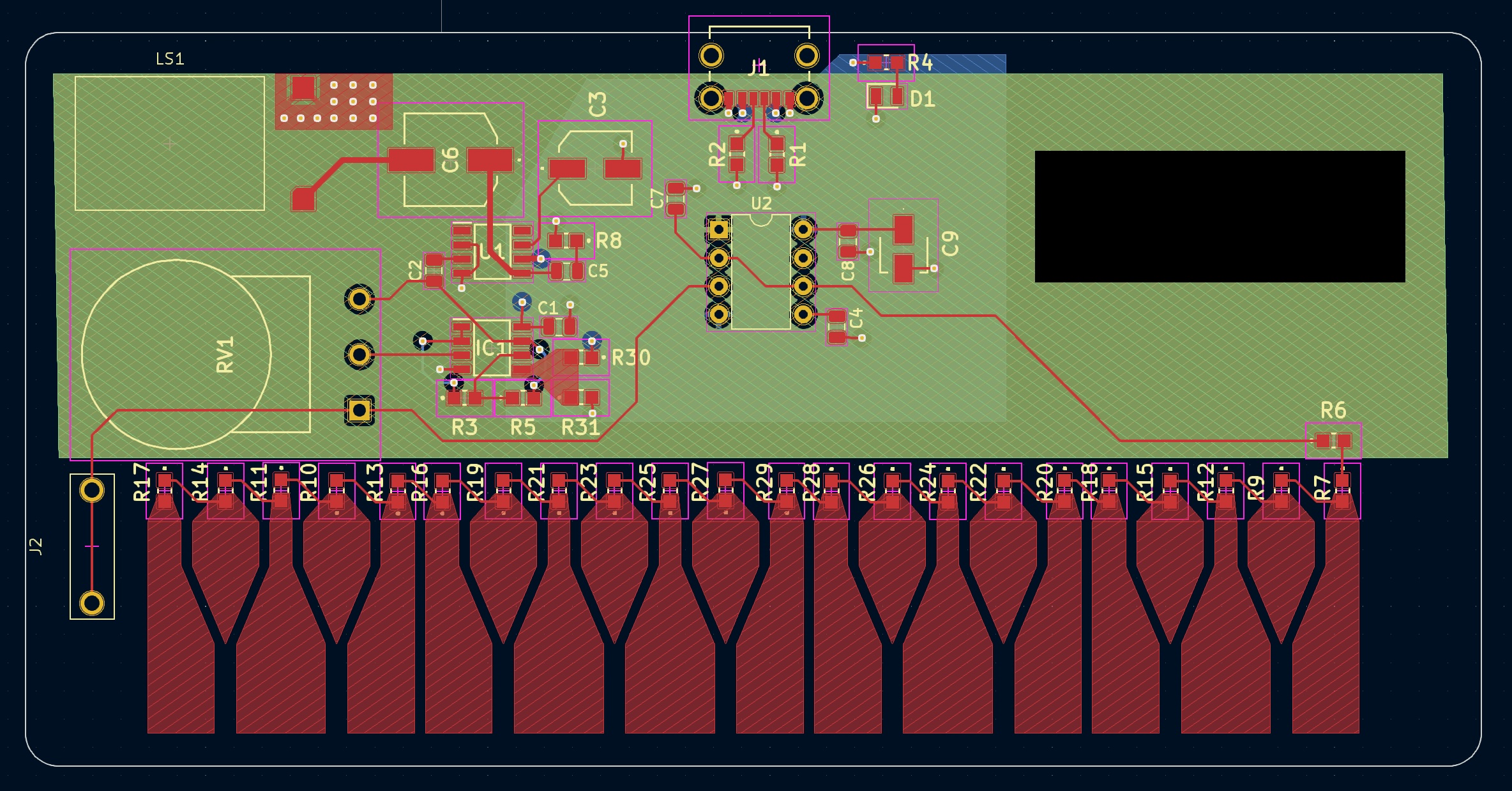
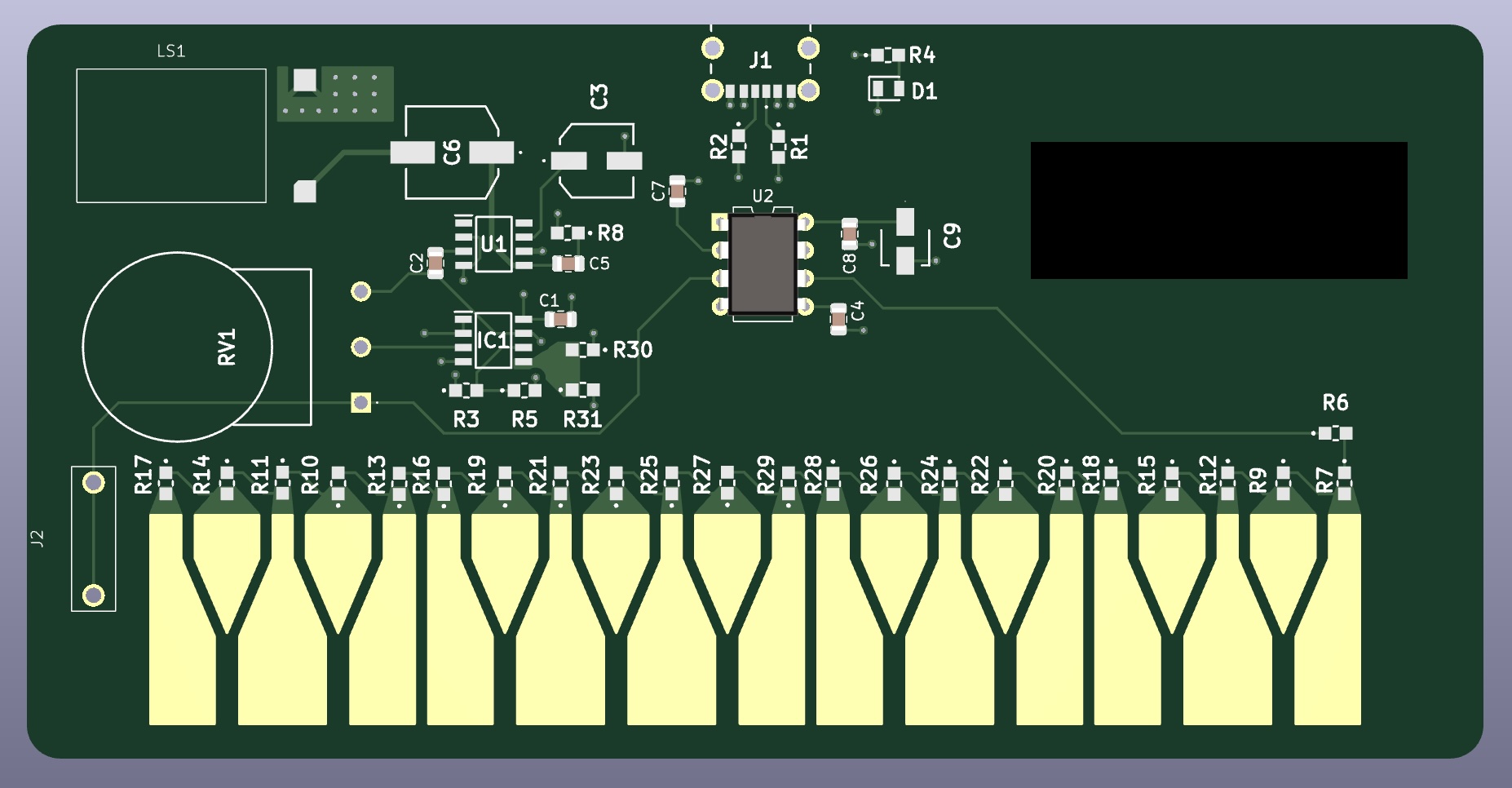
The 2-layer board was laid out in KiCAD. Power is routed and utilizes polygon pours as opposed to
dedicated power planes due to the low signal speed and low power of the design. Additionally, there
are very few components and no controlled impedances, so no more than 2 layers are needed.
Key Mistakes: Since this was one of my first boards, there were almost too many mistakes
to keep track of. Here is a non-exhaustive list of what I did wrong and what I would fix:
Problem: Many of the traces do not have a clear GND reference nearby.
Fix: Make sure each trace has GND on the layer below.
Problem: Voltage reference just uses voltage divider.
Fix: Use high impedance buffer to generate the reference voltage from divider to
prevent loading.
Problem: Placement is bad which causes awkward routing.
Fix: Rede placement so peripheral components are organized better and closer to the ICs
to minimize trace length.