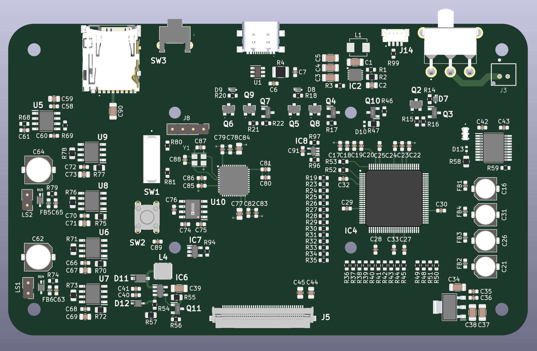
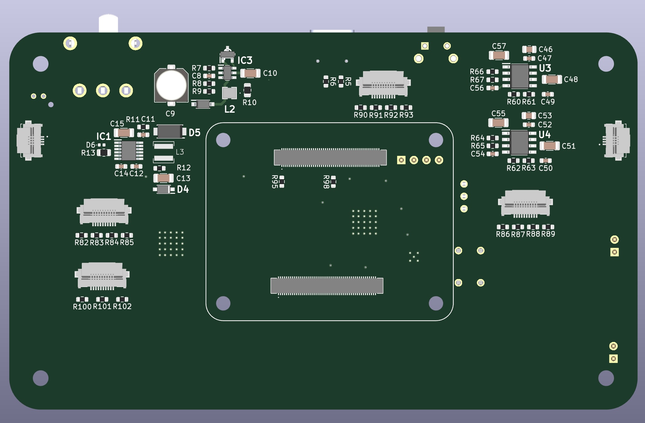
Design Overview
Hardware + Firmware
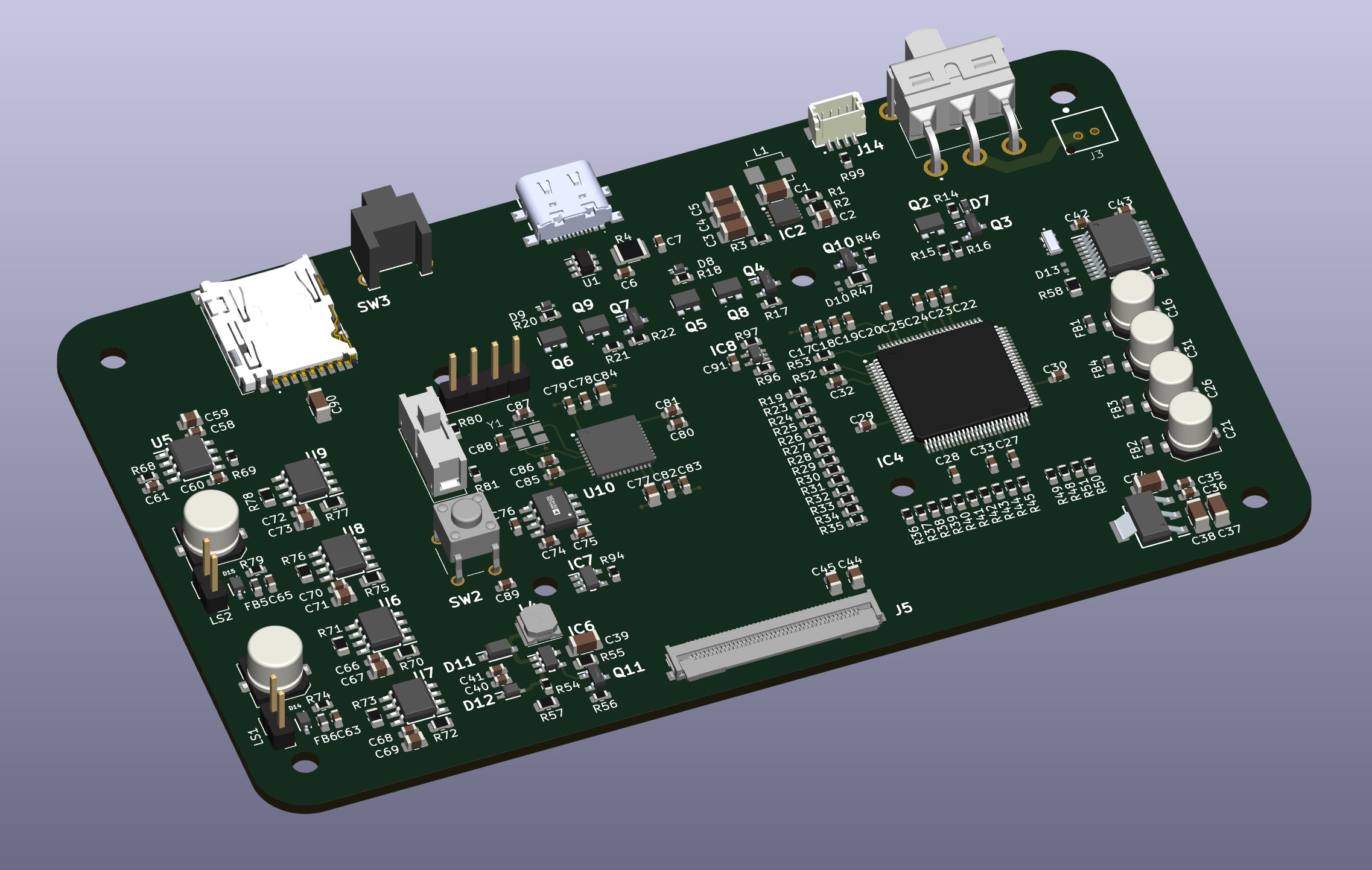
This board was designed to be the core of a retro game emulator handheld console. That means
it takes care of audio, power, display, controls, storage, and peripheral connectivity.
Hardware Integration
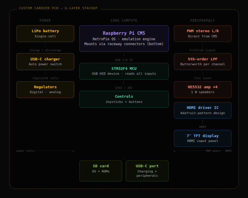
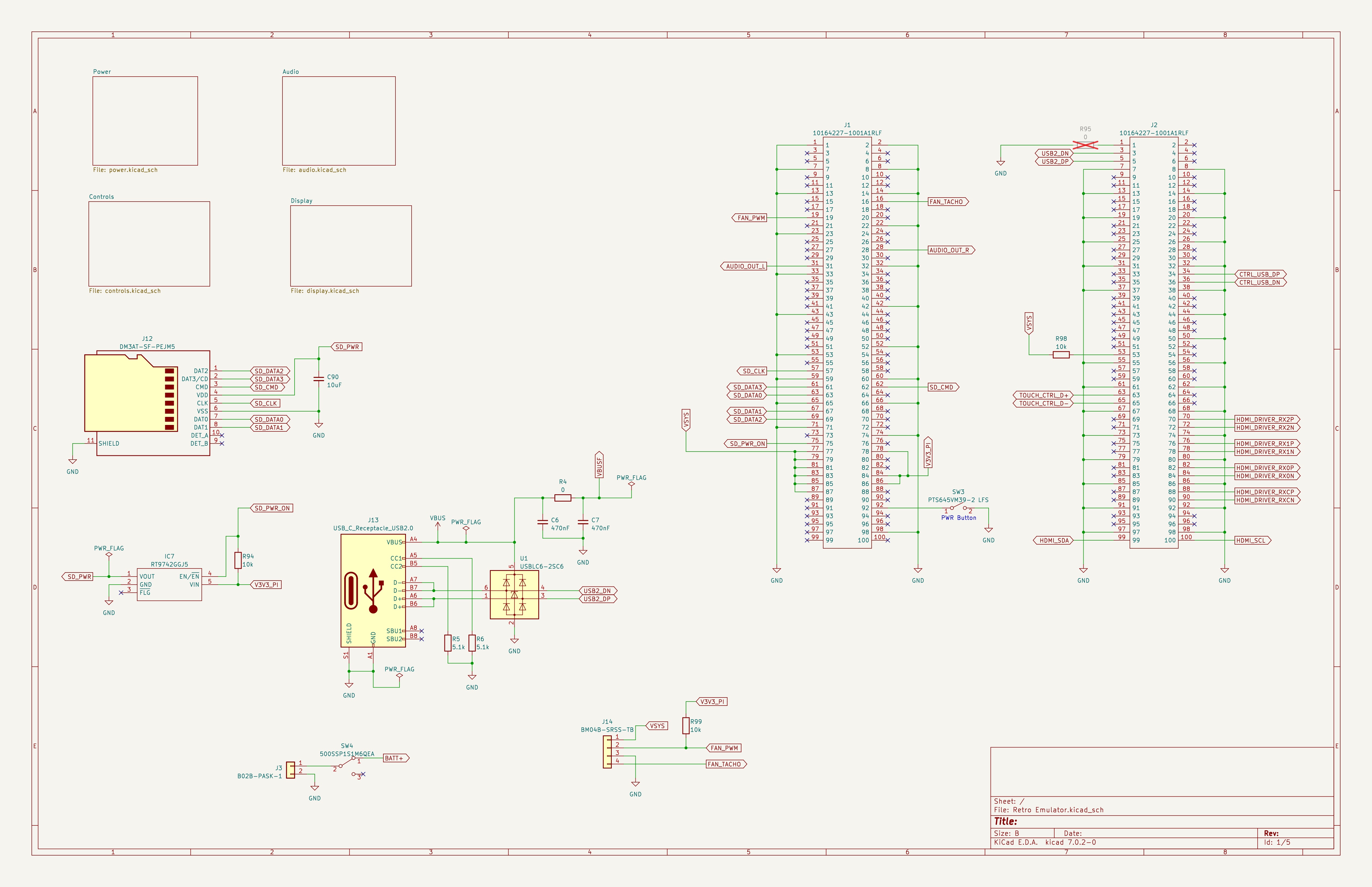
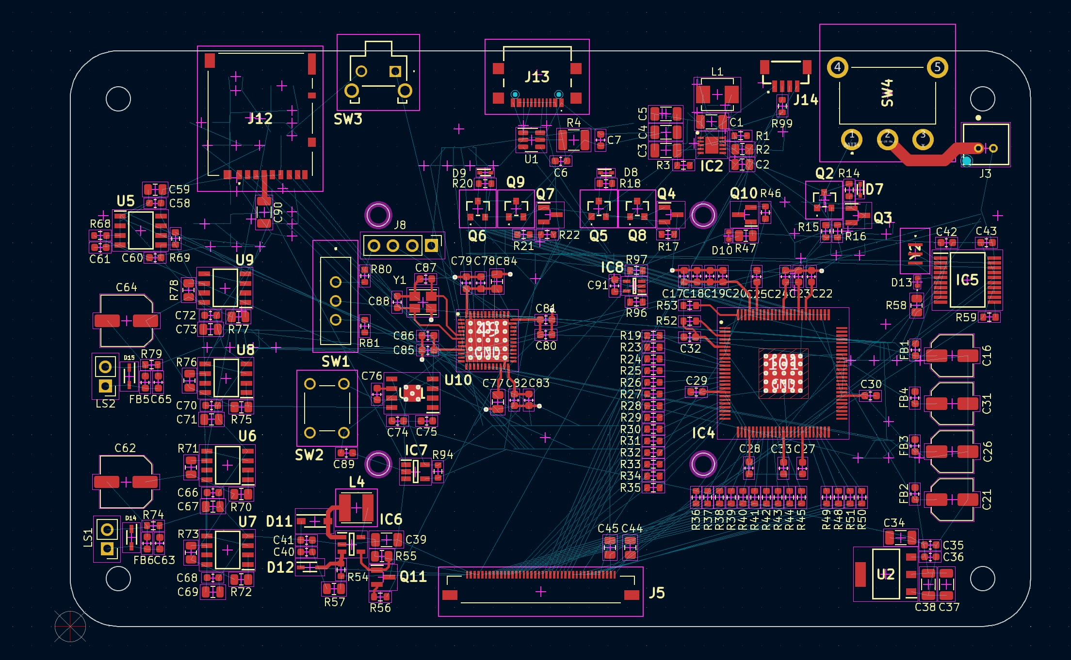
The design centers around the Raspberry Pi Compute Module 5, which mounts to the bottom of
this custom PCB via the raceway connectors. This allows for all the benefits of the RPi to
be used without the space of a tradition RPi. The RPi CM5 will be running the emulation through the
RetroPie OS. Therefore, this PCB just needs to supply the hardware necessary for a user to interact
with the game.
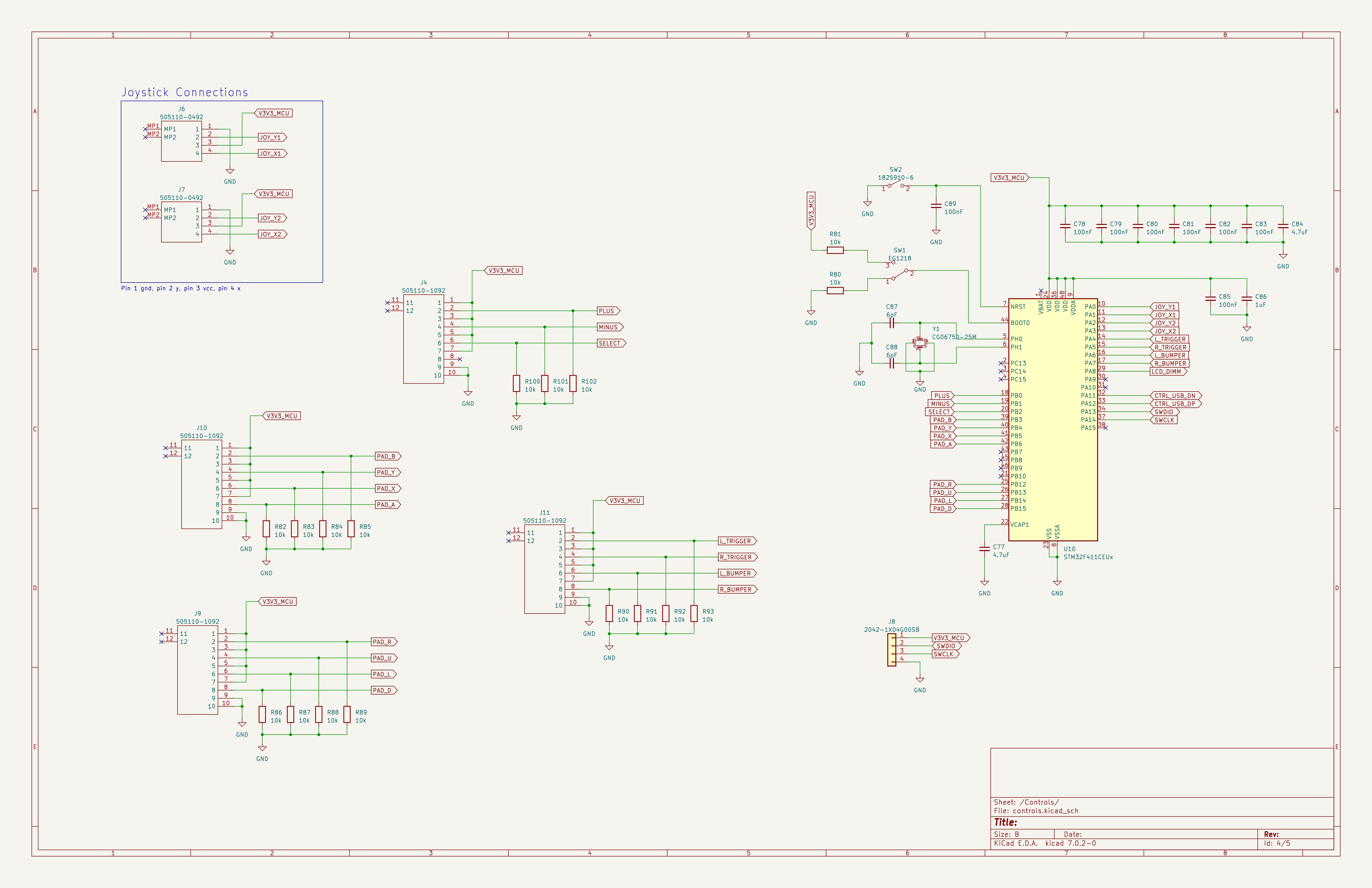
An STM32F4 MCU is configured as a USB HID device and connected to the USB 2.0 FS interface on the
RPi. It is in charge of reading all of the joysticks and button presses, and doing so through a USB
HID interface alleviates the need for many GPIO pins on the RPi itself.
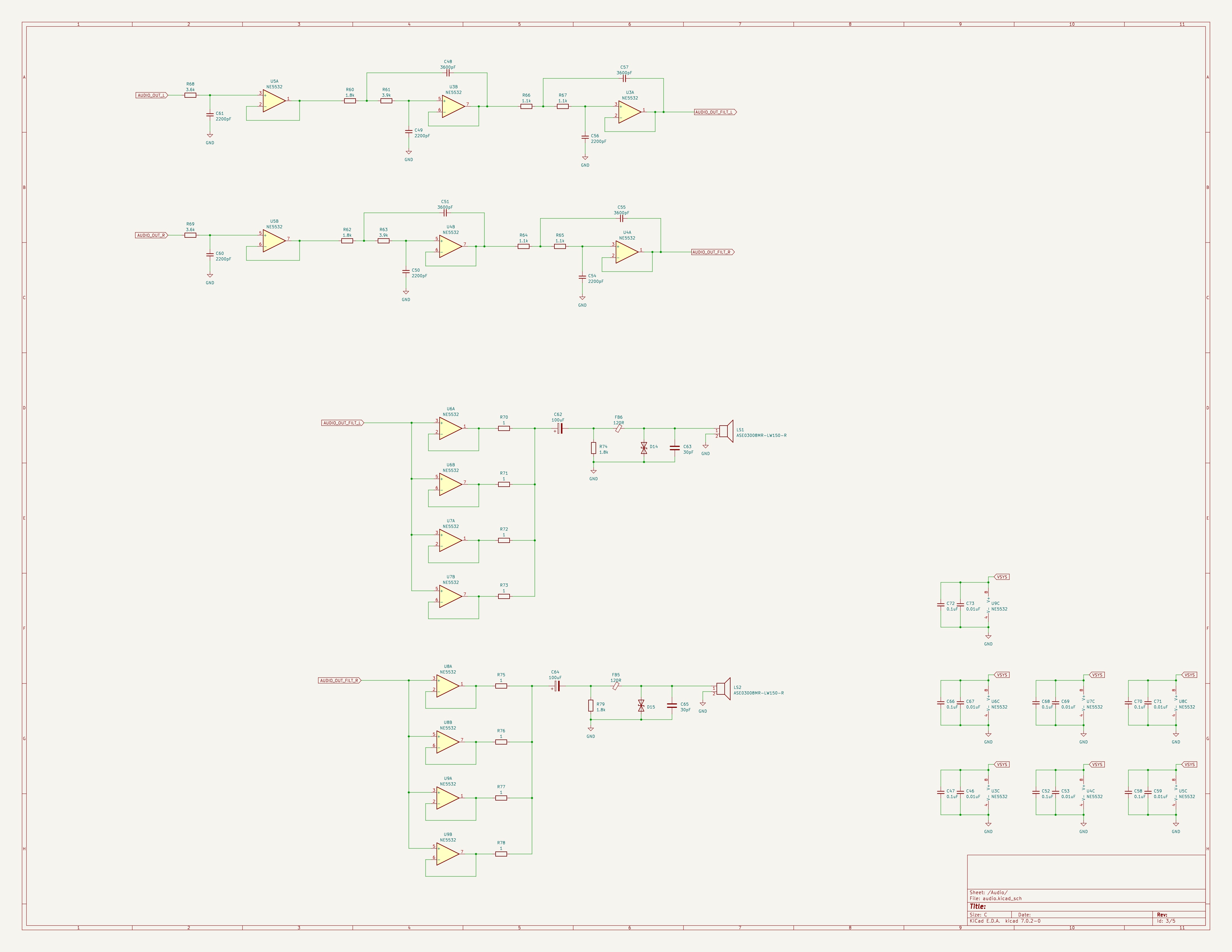
The audio circuitry is simple because hi-fidelity audio is not necessary when playing music from retro
games, so there is some wiggle room. However, I did implement stereo audio with left and right audio
PWM channels coming directly from the RPi. These lines are then filtered using a fifth order low-pass
Butterworth filter to get rid of the harsh high frequency content from the PWM. It then feeds into
four paralleled NE5532 op amps (per channel) which are meant to drive 1W speakers.
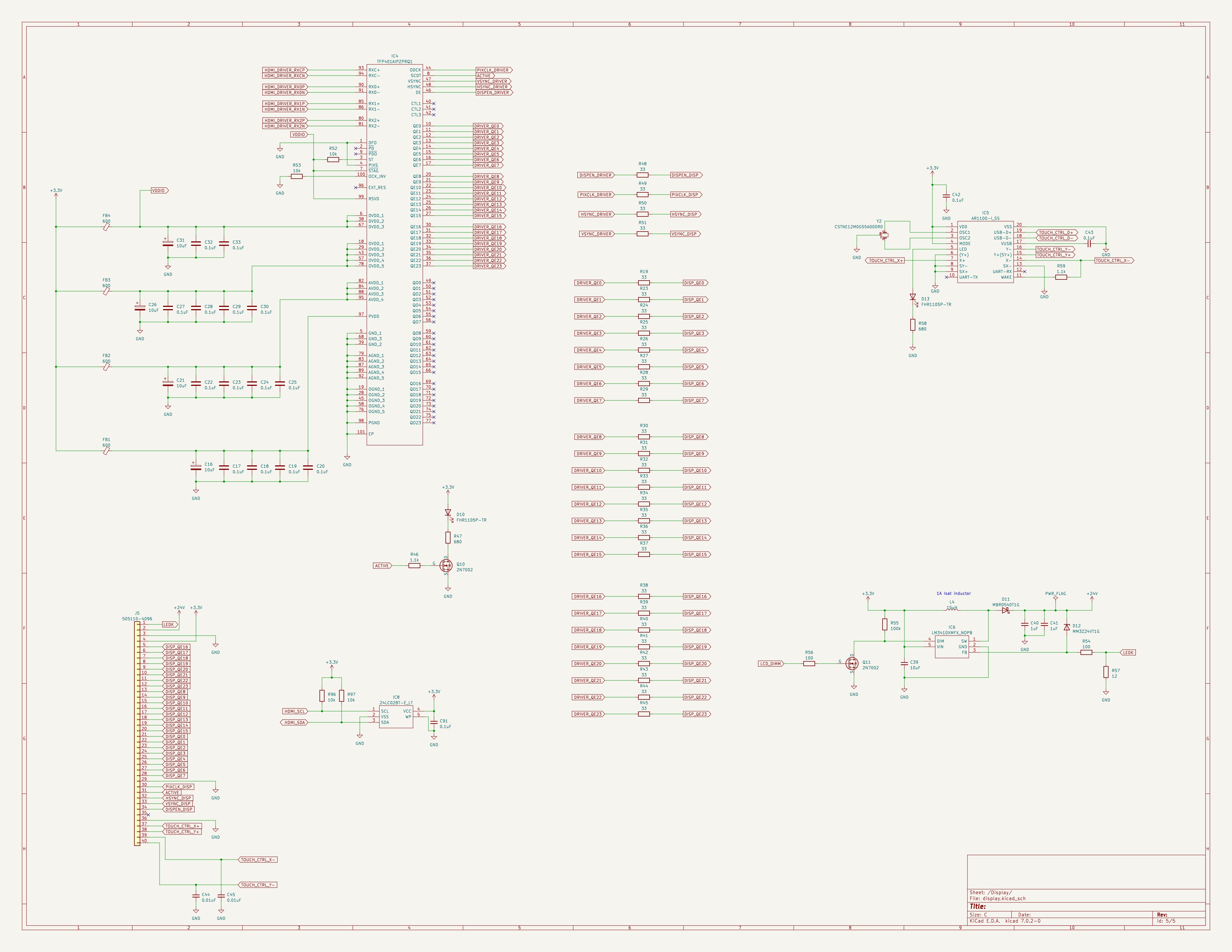
Finally, the HDMI display driver design was modeled after an Adafruit development board for one of
their 7-inch TFT displays that they sell, since the main driver IC should be plug and play with the
RPi and the display that I plan to use.
Power System
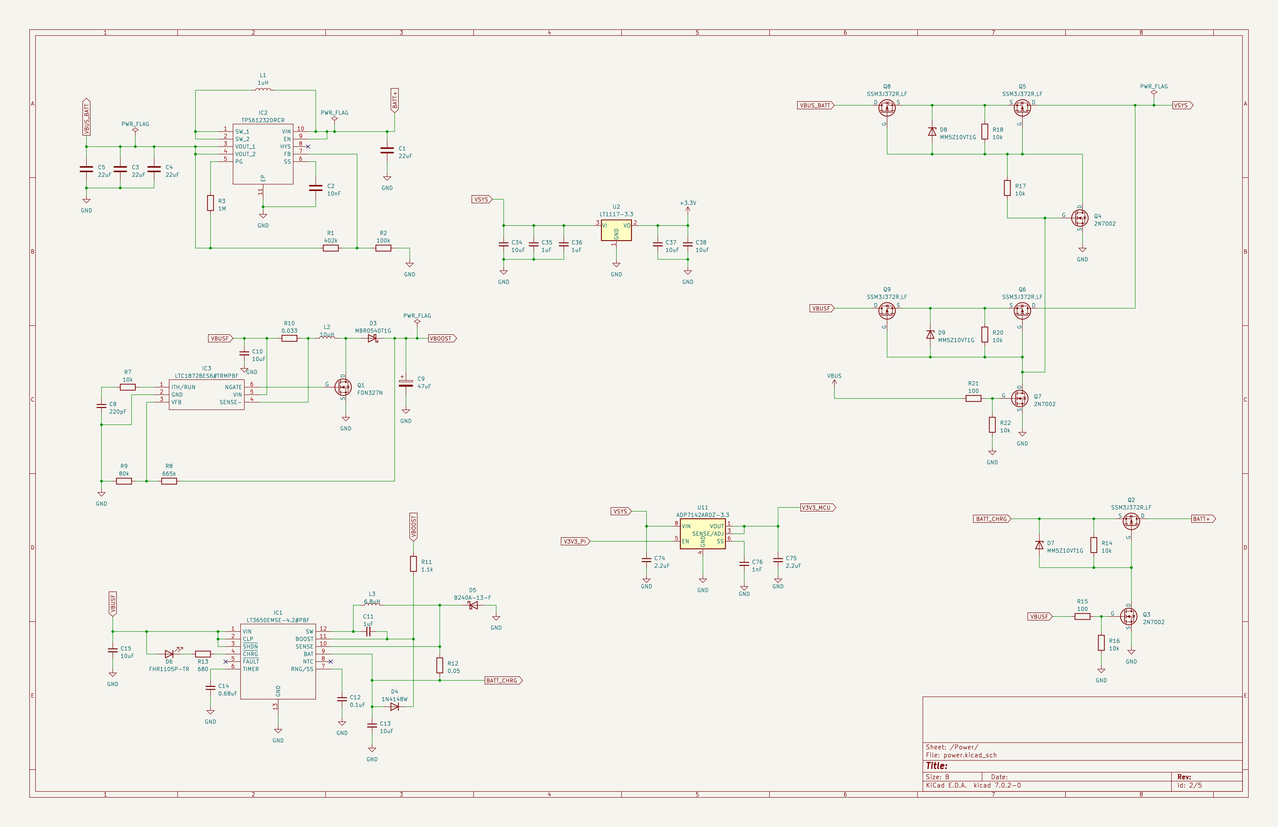
The board is powered by a single-cell LiPo battery with onboard USB-C charging
circuitry. It is designed so that it will automatically switch to USB-C power and
begin charging the battery if the cord is plugged in.
PCB Stackup
A 6-layer stackup was chosen to provide controlled impedance for USB, SD card,
and HDMI traces, solid ground referencing across all layers, and clean power
distribution. Dedicated power and ground planes minimise EMI and improve signal
integrity throughout.